Ships within 2 days via
We deliver to your doorstep under DAP terms. Customs clearance is for your account
Business customers can apply for Net 30
No fees, No interest, Fast approval.
Payment
| Item | Differential Pressure Switch |
|---|---|
| Application | HVAC |
| Approx Deadband Max. Set Point | 0.5 |
| Approx Deadband Min. Set Point | 0.4 |
| Connection Size | 1/8" |
| Connection Type | NPT |
| Contact Form | SPDT |
| Continious Pressure | 0.11 Bar |
| Electrical Connection | 3 Screw Type, Common, Normally Open, Normally Closed |
| Electrical Connection Type | Screw Terminals |
| Electrical Rating | 1/4 Hp @ 250V AC, 60 Hz, 1/8 Hp @ 125V AC, 15A @ 125/250/480V AC, 60 Hz Resistive |
| Enclosure Rating | NEMA 3, NEMA 7, NEMA 9 |
| For Pressure Type | Differential |
| Housing Material | Aluminum |
| Housing Type | NEMA-3 Enclosure |
| Includes | Drain Plug, O-Ring Seal Cover |
| Ip Rating | IP54 |
| Maximum Operating Temperature | 140°F |
| Minimum Operating Temperature | -40°F |
| Mounting Hole Center To Center Distance | 4 7/8" |
| Mounting Hole Diameter | 1/4" |
| Mounting Orientation | Vertical |
|---|---|
| Number Of Switches | 1 |
| Operating Range | 3" to 11" |
| Operating Temp. Range | -40°F to +140°F |
| Overall Depth | 3 1/2" |
| Overall Height | 3 1/2" |
| Overall Width | 5 7/16" |
| Power Requirement | 15A At 120-480V AC |
| Pressure Range | 3 in. wc to 11 in. wc |
| Pressure Set Point | 3 in. wc to 11 in. wc |
| Product Type | Differential Pressure Switch |
| Reset Type | Single Operation |
| Sample Line Connection Size | 1/8" |
| Sample Line Connection Type | NPT |
| Sample Line Connector Type | NPT |
| Surge Pressure | 0.69 Bar |
| Switch Type | SPDT |
| Switching Differential | 3 in. wc to 11 in. wc |
| Type Of Set Point | Adjustable |
| standard | CE, CSA CERTIFIED, FM, ROHS, UL LISTED |
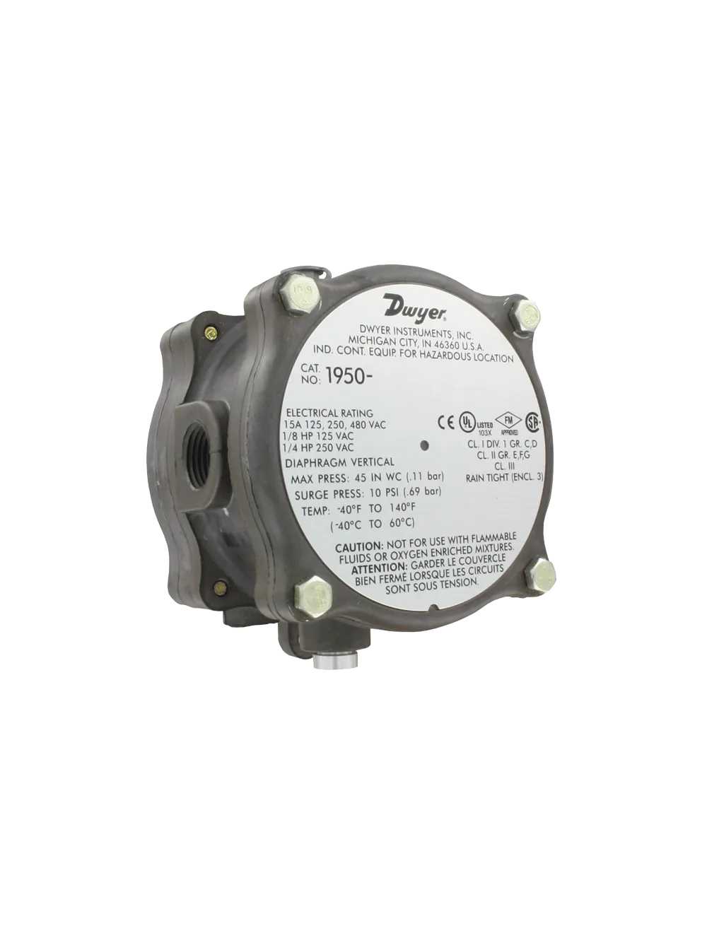
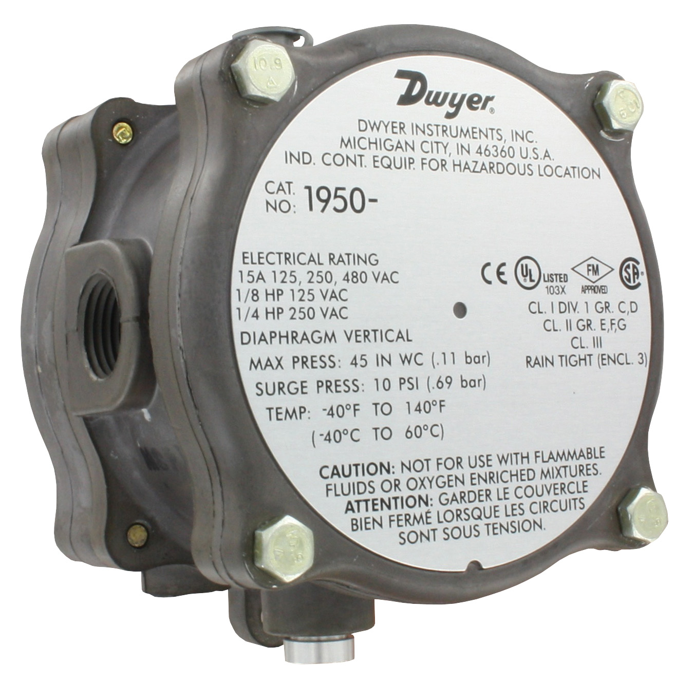
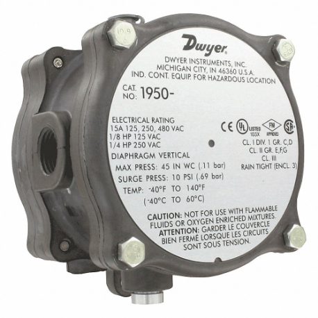
Dwyer Instruments 1950-10-2F differential pressure switch actuates electric switches in HVAC equipment through air pressure. It is equipped with an integral explosion-proof & weatherproof housing for use in hazardous environments. This switch is very light in weight & compact in size compared to other explosion-proof or weather-proof switches having separate enclosures.
| Height (cm) | 8.89 |
|---|---|
| Length (cm) | 8.89 |
| Width (cm) | 13.81 |
| Country Of Origin | US |
|---|---|
| Weight (kg) | 1.4625 |

| Style | Model | Operating Range | Connection Type | Approx Deadband Max. Set Point | Approx Deadband Min. Set Point | Ip Rating | Contact Form | Mounting Orientation | Enclosure Rating | Price (ex. VAT) | Cart |
|---|---|---|---|---|---|---|---|---|---|---|---|
| A | 1950P-15-2F | 3 psi to 15 psi | - | - | - | IP54 | SPDT | Vertical | NEMA 3, NEMA 7, NEMA 9 | $606.76 | |
| A | 1950-20-2F | - | - | - | - | IP54 | SPDT | Vertical | NEMA 3, NEMA 7, NEMA 9 | $583.86 | |
| B | 1950-0-2F | 0.15 in. wc to 0.5 in. wc | FNPT | 0.15 | 0.1 | IP54 | SPDT | Vertical | NEMA 3, NEMA 7, NEMA 9 | $598.64 | |
| B | 1950-5-2F | 1 2/5" to 5 1/2" | NPT | 0.4 | 0.3 | IP54 | SPDT | Vertical | NEMA 3, NEMA 7, NEMA 9 | $588.67 | |
| C | 1950-00-2F | - | - | - | - | IP54 | SPDT | Vertical | NEMA 3, NEMA 7, NEMA 9 | $593.59 | |
| B | 1950P-2-2F | 0.5 psi to 2 psi | NPT | 0.3 | 0.3 | IP54 | SPDT | Vertical | NEMA 3, NEMA 7, NEMA 9 | $625.50 |
Since you're visiting from the United States, for the best experience and tailored product searches, please use our dedicated U.S. website.
Go to ChatMRO.com (US)